USBAVR - An easy-to-use, universal microcontroller module featuring integrated USB, a MicroSD-Slot, and a complete software framework.
There are quite a lot of microcontroller modules around that are based on an AVR controller from Atmel. However, there are not so many designs featuring a device with integrated USB. It seems that the complexity of the USB protocol discourages a lot of people, who instead use a converter IC like the FT232RL from FTDI. This hides all of USB's complexity, but also limits its usage to a virtual serial port.
In the course of a project at the Institute for Measurement Technology at the Johannes Kepler University Linz, Austria, a new module has been developed, which should be able to provide a basis for lab experiments conducted by students. It was therefore an important requirement for the module to be robust and easy to use without experience in microcontroller programming.
I want to thank the head of the Institute for Measurement Technology, Univ.-Prof. Dipl.-Ing. Dr. Bernhard G. Zagar, and my project supervisor Dipl.-Ing. Dominik Hofer for their support.
Features
The main design goal of this project was to design an easy to use microcontroller module, which provides all the basic functionality requried in most microcontroller applications. Using this module and the provided software framework, it should be possible to setup simple applications like an SD-card datalogger in an hour or less, even for an unexperienced AVR programmer.
The main features of this module are:
- An 8bit-AVR processor with integrated USB controller running at 16MHz as the core component.
- Pin headers in DIL-spacing for easy use on a breadboard.
- Universal application by providing access to almost all IOs and thoughtful connection of on-board periphery.
- Ease of use through ordered IOs on the external interfaces and several on-board LEDs and buttons for custom usage.
- Power over USB or externally provided.
- Comfortable software framework readily providing the most-needed functionality.
- USB-bootloader for easy programming without additional programming tools.
- JTAG-interface for debugging.
- ISP-header for conventional programming, if required.
- Electrical and mechanical robustness.
- Separate headers for digital interfaces like RS232 and I2C.
- Memory card slot allowing for stand-alone measurements over long periods of time.
Pictures
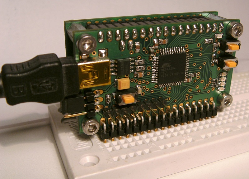 The USBAVR-Module on a breadboard, viewed from the front side. On the left, a Micro-USB cable and the power selection jumper can be seen. Next to that are the reset button and separate headers for I2C/TWI and RS232. Visible on the right side are the power LED, as well as two buttons and four LEDs, which can be utilized in user applications. On the back side, there are the MicroSD-slot, Atmel standard JTAG- and ISP-connectors, and a separate SPI-header. |
Hardware
The core component of the module is the AtMega32U4 from Atmel, which features 32kB of flash memory, an integrated USB-controller,
as well as many other integrated periphals in a small 44-pin TQFP package. Almost all parts are SMD, allowing for a small board size of
56x32mm.
A sandwich design with two vertically aligned double-layer boards was chosen for the following reasons:
- Small footprint, allowing for comfortable use on a breadboard.
- Two accessible layers for placing of headers and control elements like buttons and LEDs, even trough-hole parts.
- Four copper layers allowing for efficient routing and parts placement.
- High mechanical stability.
- Functional separation of the boards allows for individual testing.
The only major drawback of this design is the higher production cost due to requiring two different boards.
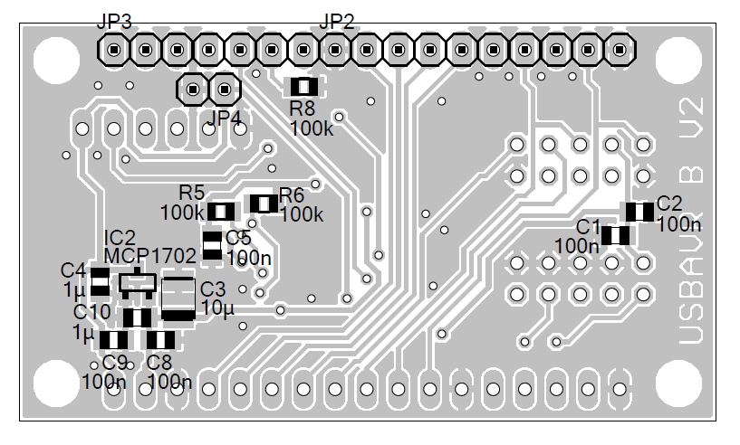
A-board
The A-board accomodates the core component, the AtMega32U4 from Atmel. All the necessary parts for basic operation of the microcontroller are located on this board too. This includes power supply and selection of the power source, the Micro-USB interface connector with accompanying ESD protection, and the Quartz. Additionally, two debounced buttons and four LEDs are available for user programs, as well as the power indicator LED and the reset button. This design allows operation (and testing, of course) of the A-board without the B-board.
For additional comfort, the RS232 and I2C/TWI data lines are available on dedicated headers, along with GND and VCC. The angled 17-pin pin header acts as the external interface and provides all 8 IOs of Port D, and four IO lines of Port B, in ordered arrangement. Pin 1 can be used to provide 5V if USB bus power is not available or not desired, Pin 2 allows to reset the controller by an external source, and Pin 17 is GND. The rest of the IO lines is routed to the B-board by functionally separated headers.
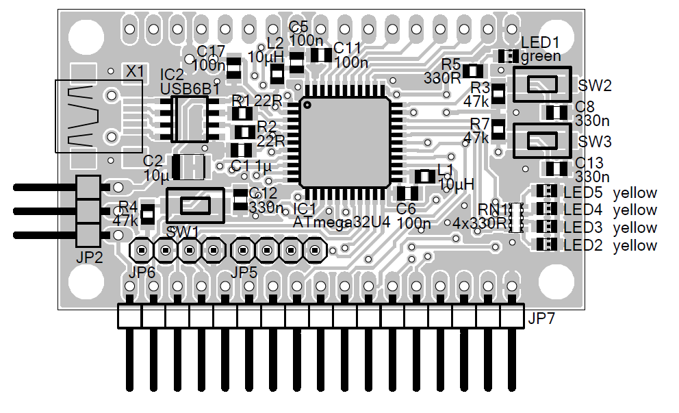 A-board top layer and part placement. |
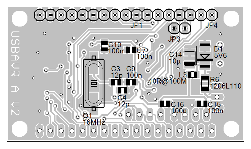 A-board bottom layer and part placement (mirrored horizontally). |
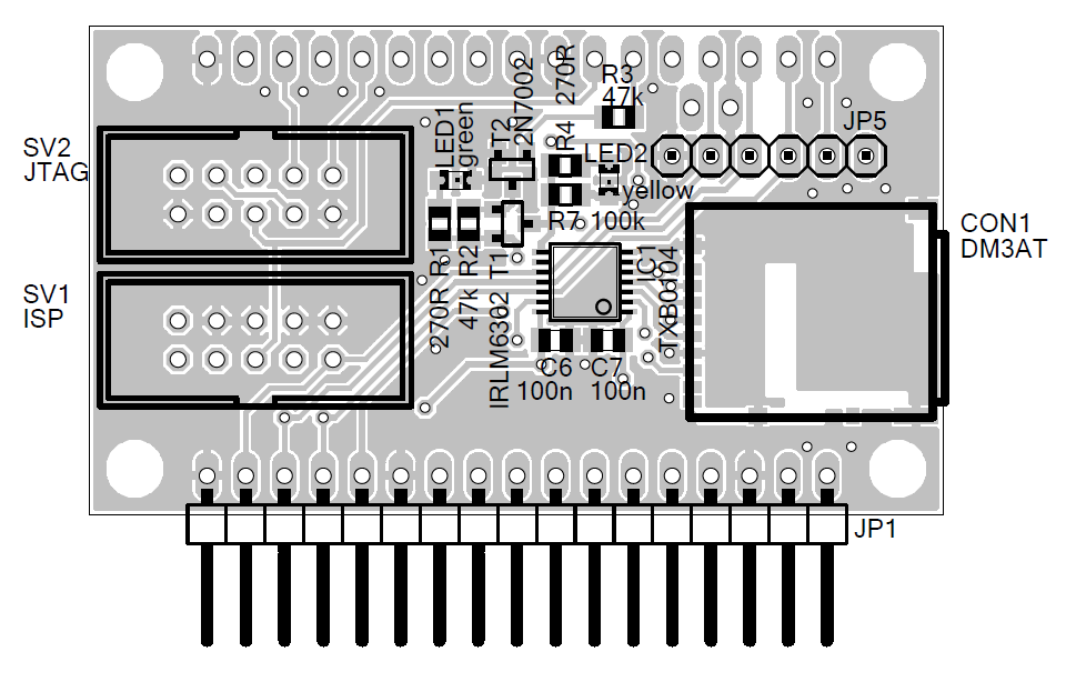
B-board
Besides housing the MicroSD slot, the B-board's main purpose is providing space for the large ISP- and JTAG-connectors. The 3.3V required for the operation of the MicroSD slot are generated on-board by a low-drop regulator. This voltage is additionally available on pin 2 of the 17-pin angled header, which eliminates the need for an external power source when using 3.3V electronics with the module. A LED indicates if the voltage is present. On pin 1, the 5V system voltage is available from the source selected by the jumper on the A-board, and pin 17 is GND again.
All IO lines that can handle analog signals are available on pins 4-11, surrounded by GND pins for comfort and shielding. The remaining four
pins of PortB are routed to pins 13-16.
The SPI interface is available on a dedicated header, again along with VCC and GND. However, the SPI interface is used for communication with
the MicroSD card. To allow concurrent use, PB4 is used as /CS for the MicroSD card and PD5 controls power to the SD card. The latter can be
used to hard-reset the card, and additionally the level-shifter disconnects the card slot entirely when power is swiched off. A separate LED
indicates if the SD card is powered.
As mentioned, ISP and JTAG are available on two separate 10-pin box headers with Atmel standard pinout. However, tt is recommended to only equip of those to prevent confusion and damage to the module and programming hardware. Additionally, a second version of the B-board is available, which features the 6-pin ISP header favoured by Atmel. Note that 6-pin box headers are sometimes not so easy to get as the 10-pin version. See the downloads section.
 B-board top layer and part placement. |
 B-board bottom layer and part placement (mirrored horizontally). |
Servo Expander
The USBAVR module can easily be used to control RC servos. Using some additional circuitry, it is possible to control up to nine RC servos using only one PWM output and one additional IO pin. Only some lines of code are required and the code is not especially time critical. The only element required is a 4017 decade counter IC; the circuit is the same as in many old RC receivers - see the schematic on the right. Note that Q0 is not used, as this output gets activated with the reset pulse, which has to be generated in software on an IO pin. The clock (which is generated by a PWM output) shifts the output from Q0 through Q9, which means that the pulse on Q0 is started in software by the reset signal and ended by the first timer compare match in hardware. This makes it difficult to achieve exact timing on Q0, whereas all other pulse widths are controlled entirely in hardware, yielding the required accuracy.
RC servos are controlled by a PWM signal, with the pulse width (high level) indicating the desired position. The pulse width must be between 1ms and 2ms, where 1ms means full left and 2ms means full right. The pulse repetition rate should be around 50Hz.
The basic algorithm to control a number of servos is simple: After resetting the counter with a high pulse on the reset line, Q0 is active. The first rising edge on the clock input starts the pulse for the first servo on Q1 and each subsequent rising edge ends the pulse for the current servo and starts the pulse for the next one. This can be achieved in some ways, for example by simply using the output compare mode of a hardware timer with the mode set to "set on compare match". Set the compare match register for example to 0x0001 so that the first timer cycle starts the pulse for the first servo. In the compare match interrupt just add the number of timer ticks representing the desired pulse width for the current servo to the compare match register and then clear the output in software. After the last servo you will have to implement some logic to reset the counter and start over with the first servo. Optionally, you could leave out the reset pulse and just let the counter overflow to Q0 after Q9. This would allow you to use Q0 in the same manner as Q1-Q9 and therefore to control ten servos.
Software
One of the most important features of the USBAVR module is the accompanying software framework, which significantly distinguishes this project from at least some of the other alternatives around. It provides the user with most of the commonly required functionality, allowing to focus on the desired functionality. Additionally, large parts of the framework can be configured according to your needs and to save flash memory when certain functions are not used.
Features
While some basic functionality is required in almost any microcontroller project (and often coded from scratch every time), some more advanced things would often be nice to have, but require too much effort for smaller projects. This is the reason why the software framework readily provides the following features:
- Virtual serial port over USB.
- FAT16 file system access to the MicroSD card.
- MicroSD card can be accessed from the host PC as mass storage device (concurrently with virtual serial port).
- Automatic button handling with callback of user functions on button press/down/up/hold.
- Comfortable functions and macros for control of LEDs, ADC, and output of several data types over RS232 (hardware and virtual).
- Simple command shell providing read/write access to variables and calling of functions.
- System timer with 1ms resolution and a basic task scheduling system (i.e. run a function every 100ms).
- Automatic loading of user configuration data from EEPROM at startup (config can be stored by shell command).
Modules
The framework is split into several modules, which provide functions for different tasks. Many projects will only require changes to the
files usercode.c and usercode.h, which encapsulate the user application code. Only special applications will make it
necessary to even mess around with the main loop or other parts of the framework.
Look at the example functions in these files to see how it works; it should be quite self-explanatory.
The following example functions are implemented:
- Periodic reading of ADC channels 4,5, and 6 (for 3-axis accelerometer) using the provided task functionality.
- Logging task can be startet and stopped by button press (callback function) or shell command.
- Output of the read values over virtual serial port in hex format.
- Logging of these values to file log.txt on MicroSD-card in CSV-format.
- MicroSD is accessible as mass storage device when currently not logging.
- RC servo control demonstrating the use of a 10bit-timer.
- LED blinking using separate periodic task.
- Basic functionality like reading and setting variables via shell.
 Without doubt, the most important task of the software framework is the handling of the USB communication. This is done by
Dean Camera's great LUFA library. The module can be configured
to act as a simple virtual serial port, or as a compound device featuring a virtual serial port and a mass storage device for access to
the MicroSD card. Driver .inf-files for Microsoft Windows are provided with the software and do not require driver signing.
Without doubt, the most important task of the software framework is the handling of the USB communication. This is done by
Dean Camera's great LUFA library. The module can be configured
to act as a simple virtual serial port, or as a compound device featuring a virtual serial port and a mass storage device for access to
the MicroSD card. Driver .inf-files for Microsoft Windows are provided with the software and do not require driver signing.
File system access to the MicroSD is implemented by Roland Riegel's lightweight but powerful MMC/SD/SDHC card library. As this functionality requires quite a decent amount of flash memory, it can optionally be disabled too.
Most of the code should be easy to understand and is quite well documented with inline comments; some parts additionally feature doxygen documentation. The latter is escpecially true for the configuration file config.h which controls the behaviour of the framework by means of several preprocessor macros. Valid values for some settings can be found in config_options.h
Shell
The integrated shell supports the following commands (if an unknown command is entered, a list of available commands is output):
- get [var] [x|h] Outputs a list of all registered variables when called without parameters. If a variable name is given, the value of this variable is output. When x or h is given as the second parameter, integers are output in Hex format.
- set <var> <value> Sets a registered variable to the given value. Integers can be given in Hex format if 0x is prepended.
- call [func] [params] Calls a registered user function with the provided parameters. If no function is specified, a list of all registered user functions is output.
- sdinit Initializes the memory card.
- sdinfo Outputs some info on the MicroSD card in the slot.
- loadcfg Loads the user configuration from the EEPROM. This can be useful to reset values that were changed throuh the shell.
- savecfg Stores the user configuration to the EEPROM. This is never done automatically and has to be forced by this shell command. This configuration is the loaded on the next startup.
- defcfg Loads the default configuration as defined in the user code. This is not the same as loading it from the EEPROM.
Bootloader Programming
Atmel delivers these microcontrollers with a preprogrammed bootloader. After building the framework with WinAVR, the binary can be programmed into the microcontroller with Atmel's FLIP program. To execute the bootloader, the button T1/HWB has to be held down while resetting the controller. The board will then be enumerated by the host PC as an Atmel DFU device or AtMega32U4 and is ready to be programmed.
Downloads
Hardware
- A-Board Schematics, Layout, and Eagle files
- B-Board (10pin-ISP-Header) Schematics, Layout, and Eagle files
- B-Board (6pin-ISP-Header) Schematics, Layout, and Eagle files
- Excel part list (in German) with Farnell or RS Components ordering numbers (Warning: Common parts like resistors are not listed with suppliers, some parts may missing, and the list itselft may be outdated!)
Firmware
Dean Camera's LUFA Library is required to compile this source code. The version used for development is 100807. Newer versions may require some changes to the makefile or the source files. See readme.txt for instructions on the required directory structure.
Documentation
Bugs and Improvements
As with every project, it is very likely that there are still some bugs and flaws in the software or the hardware. Additionally, there is definitely room for improvement. If you encounter bugs or have comments on the project, please contact me at
Copyright 2010, 2011 by Martin Degelsegger
 USBAVR is free software/hardware: you can redistribute it and/or modify
it under the terms of the GNU General Public License as published by
the Free Software Foundation, either version 3 of the License
(http://www.gnu.org/licenses/gpl.html),
or (at your option) any later version.
USBAVR is free software/hardware: you can redistribute it and/or modify
it under the terms of the GNU General Public License as published by
the Free Software Foundation, either version 3 of the License
(http://www.gnu.org/licenses/gpl.html),
or (at your option) any later version.
USBAVR is distributed in the hope that it will be useful, but WITHOUT ANY WARRANTY; without even the implied warranty of MERCHANTABILITY or FITNESS FOR A PARTICULAR PURPOSE. See the GNU General Public License for more details.
Disclosure according to §25 MedienG 2005:
Information page for the USBAVR mikrocontroller project
Operated by: Martin Degelsegger, Linz
